The Operator's First Five Minutes
The Operator's First Five Minutes: Designing HMIs for Rapid Fault Recovery
When a complex industrial machine abruptly stops, the countdown begins immediately. In high-speed manufacturing environments, every minute of lost production represents hundreds or thousands of dollars in wasted overhead and missed delivery deadlines.
Yet, during an unexpected stoppage, the single most critical factor determining how long the line stays down is not the speed of the maintenance technician’s wrench; it is the cognitive experience of the machine operator during the first five minutes of the fault.
Consider what typically happens when a line trips: a loud alarm horn sounds, a red beacon flashes, and the operator walks up to the HMI screen. If the control system is poorly designed, the screen is flooded with 40 simultaneous, flashing red alarms. The text on the primary banner reads:
FAULT BIT 0x4A2 - INTERLOCK TIMEOUT DSR-01
.
The operator has no idea which physical station faulted, where the product is jammed, or what safety circuit opened. They clear the alarm buffer, press reset, watch the machine fail to start, open five random safety doors searching for a jam, and finally walk away to find a maintenance technician.
Ten minutes are lost before diagnostic work even begins.
Designing control systems and HMI screens specifically for the operator's first five minutes is the highest-leverage engineering optimization you can make to cut Mean Time To Repair (MTTR). Here is how traditional HMI designs fail operators during critical stoppage windows, and how to engineer an interface that drives rapid, error-free fault recovery.
Mistake #1: The Post-Trip "Alarm Blizzard"
Why it happens: When a packaging machine or robotic cell trips an Emergency Stop or main safety interlock, dozens of downstream devices lose power or drop their ready signals simultaneously. If the PLC code is not architected with alarm filtering, the HMI screen displays an alarm for every single device that lost its run-enable signal.
What it costs: Cognitive paralysis. The operator is presented with a wall of 30 flashing red alarms:
Vacuum Pump Off
,
Infeed Drive Not Ready
,
Discharge Jam
,
Safety Circuit Open
,
Heater Contactor Dropped
.
The operator cannot distinguish between the primary initiating event and the 29 harmless derivative faults caused by the shutdown sequence. Frustrated, they acknowledge all alarms at once, wiping the screen clean and erasing the diagnostic clues needed to fix the problem.
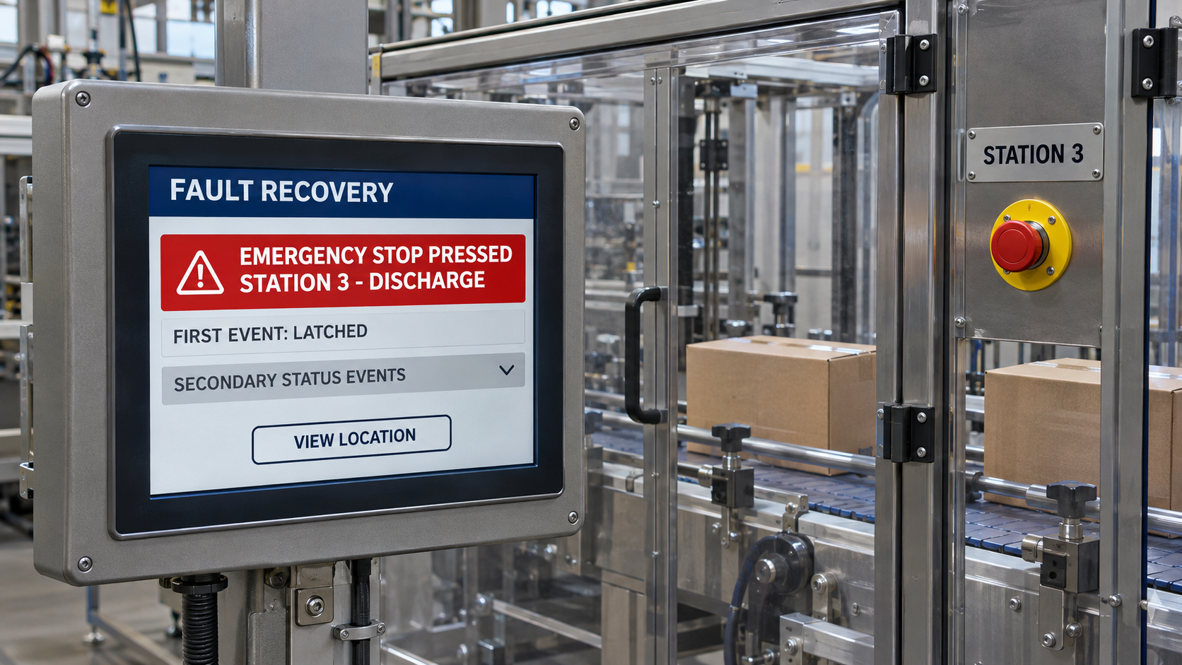
The fix: Implement dynamic alarm suppression and "First-Out" visual hierarchy in the PLC and SCADA layer. When a safety circuit or initiating sensor trips, the PLC must immediately latch that root fault and suppress all downstream secondary alarms.
The HMI must display
one single, high-priority alarm banner highlighting the initiating event: e.g.,
EMERGENCY STOP PRESSED: STATION 3 (DISCHARGE)
. All secondary status changes are demoted to low-priority info banners, instantly focusing the operator's attention on the exact physical location of the stoppage.
Mistake #2: Cryptic Engineering Tags Instead of Plain-Language Instructions
Why it happens: Controls engineers program the HMI using the exact tag names from the PLC ladder logic:
PE_102_FLT
,
MTR_4_OL
,
PROXY_EXT_TO
. It makes perfect sense to the engineer who spent three weeks writing the code, but it is completely incomprehensible to a line operator or new hire.
What it costs: Unnecessary maintenance dispatches. An operator faced with
PE_102_FLT
will immediately call an electrical technician.
When the technician arrives fifteen minutes later, they locate
PE_102
on the electrical prints, walk over to the machine, wipe a smudge of dust off the optical photo-eye lens with their thumb, and press reset. A stoppage that should have taken 20 seconds to clear consumed 20 minutes of line capacity and burned skilled maintenance hours on a trivial housekeeping task.
The fix: Enforce a strict plain-language HMI alarm standard that provides three distinct pieces of information for every fault:
- What happened (in plain English): "Carton Infeed Photo-Eye Blocked."
- Where it happened: "Station 2, Infeed Rail (South Side)."
- How to fix it: "Check for jammed cartons. Clean sensor lens if clear. Press Reset on Console 2."
Empowered Automation builds interactive help screens directly into HMI alarm banners: tapping the alarm brings up a physical photo or 3D isometric layout of the machine showing the exact physical location of the sensor, allowing operators to locate and resolve the issue in seconds.
Mistake #3: Buried Manual Jog and Clear Controls
Why it happens: To recover from a mechanical jam, an operator frequently needs to perform a manual sequence: open a pneumatic gripper, reverse an infeed conveyor, or jog a starwheel a few degrees to clear the jammed packaging.
In poorly architected HMIs, these manual controls are buried four levels deep inside password-protected "Engineering" or "Maintenance" sub-menus.
What it costs: Operators are either locked out from performing basic clearing actions, or they spend several minutes clicking through confusing navigation trees trying to find the manual jog screen.
In many plants, operators bypass the HMI entirely: they grab a pry bar or screwdriver and physically force mechanical components backwards, damaging drive shafts, bending linkages, and stripping timing belts.
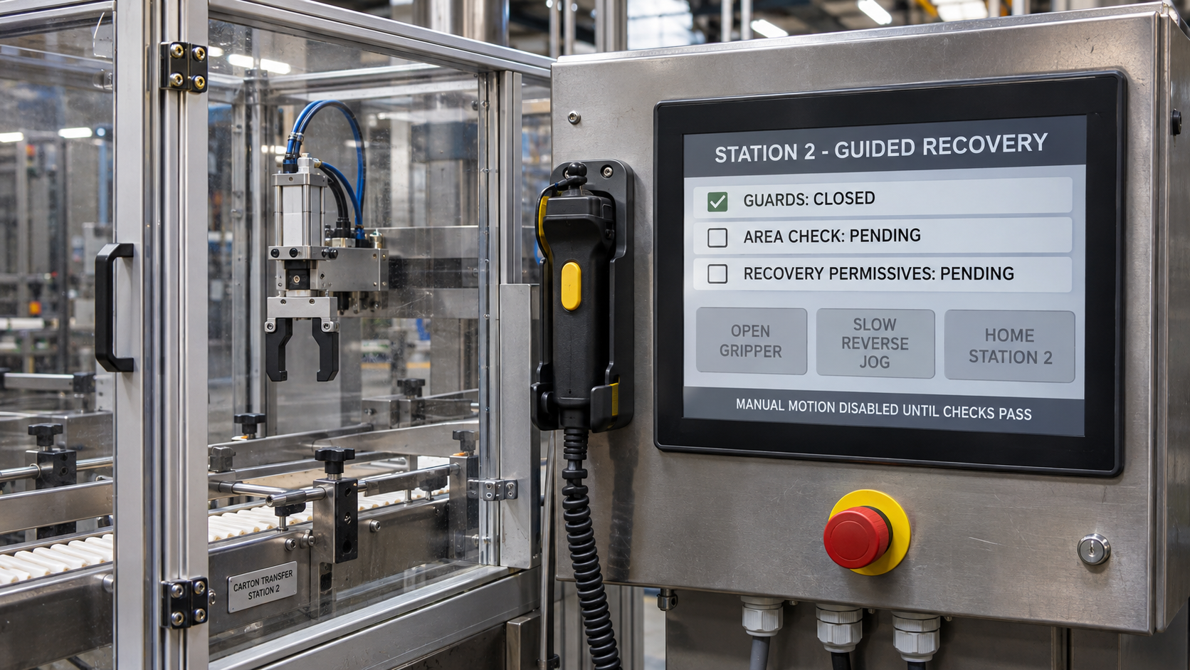
The fix: Build contextual, one-touch "Recovery Workflows" into the HMI fault screen. When a specific station trips on a jam, the HMI should automatically present a contextual "Jam Clearing" overlay.
This screen presents only the specific manual controls required to recover that specific station: e.g.,
Open Gripper 3
,
Jog Infeed Reverse (Slow)
. Once the jam is physically cleared and the sensor confirms the zone is empty, the screen automatically transitions to a guided
Home Station
button.
No sub-menus, no hunting for controls, and no engineering passwords required for standard operational recovery.
Mistake #4: Forcing Destructive Home Routines and Power Cycles
Why it happens: In many legacy PLC programs, the machine homing sequence is written with rigid, uncoordinated logic. If an operator hits an E-stop to clear a minor jam, the PLC loses absolute position tracking on its servo axes.
When the machine is restarted, the PLC forces a full "Global Home" sequence: all axes must travel back to their physical limit switches, regardless of where they are currently positioned.
What it costs: Catastrophic mechanical collisions and extended downtime. If an operator has not cleared every piece of product from the cell, a blind homing routine will drive servo tooling directly into jammed containers or structural frames, breaking mechanical arms and bending shafts.
Furthermore, running a full home routine on a complex line can take 10 to 15 minutes of slow-speed axis hunting, dramatically inflating MTTR for a simple stoppage.
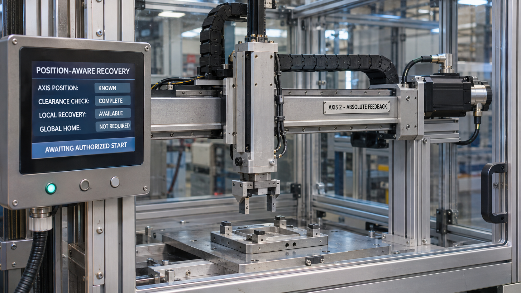
The fix: Implement intelligent, position-aware recovery routines in the PLC code. Utilize absolute encoders on servo axes so the control system never loses physical position, even through a complete power cycle or emergency stop.
Program "Intelligent Clear" sequences that verify all axes are clear of interference zones before homing, and allow operators to resume production directly from the stopped position whenever safe, bypassing the homing cycle entirely.
The Anatomy of a High-Recovery HMI Screen
A high-performance HMI screen designed for rapid operator recovery prioritizes clarity, context, and immediate action:
┌────────────────────────────────────────────────────────────────────────┐
│ ACTIVE ALARM: Infeed Starwheel Jam [Station 2] [HELP] │
├────────────────────────────────────────────────────────────────────────┤
│ │
│ [ Machine Graphic ] Recovery Checklist: │
│ Highlighting Station 2 in RED 1. Inspect Starwheel Pockets. │
│ Photo-Eye PE-204 Status: BLOCKED 2. Clear jammed containers. │
│ 3. Verify sensor lens clear. │
│ │
├────────────────────────────────────────────────────────────────────────┤
│ Contextual Recovery Controls: │
│ [ OPEN STARWHEEL CLAMP ] [ JOG REVERSE (SLOW) ] [ HOME STATION 2] │
└────────────────────────────────────────────────────────────────────────┘
Operator Recovery Design Audit Checklist
Evaluate whether your plant's HMI and control architecture empowers operators during the critical first five minutes:
- [ ] First-Out Filtering: Does your HMI display a single root-cause alarm banner, suppressing secondary cascaded faults?
- [ ] Plain-Language Text: Are alarm messages free of cryptic PLC tags, providing clear descriptions of what faulted and where?
- [ ] Visual Mapping: Does the HMI show an intuitive physical graphic indicating the exact location of the faulted sensor or component?
- [ ] Contextual Controls: Can operators access manual jog and clear controls directly from the fault screen without digging through sub-menus?
- [ ] Non-Destructive Recovery: Does the control system retain absolute position through E-stops, avoiding forced global homing routines?
Conclusion
The first five minutes following an unexpected stoppage determine whether an event becomes a minor 60-second blip or a 30-minute operational disaster. When operators are confronted with alarm blizzards, cryptic hexadecimal fault codes, and buried recovery controls, they are set up to fail.
By engineering your PLC alarm logic for first-out trapping, adopting plain-language diagnostic standards, and providing guided, one-touch recovery workflows on the HMI, you empower line operators to diagnose and clear faults independently, driving Mean Time To Repair down and keeping your production running at peak capacity.
Ready to Optimize Your Plant’s HMI and Control Systems?
Empowered Automation Solutions designs operator-centric HMI and SCADA systems that maximize plant floor efficiency. From refactoring complex PLC alarm structures and designing intuitive, graphic-rich HMI interfaces to implementing intelligent servo recovery routines, our team builds control systems that make troubleshooting fast, intuitive, and safe.
Contact our controls engineering team to evaluate your human-machine interfaces:
- Phone: (630) 553-0411
- Email: info@empoweredautomation.com
- Address: 1905 Marketview Dr., Suite 138, Yorkville, IL 60560
Frequently Asked Questions
What is the ISA-101 standard for HMI design?
ISA-101 is an international standard focused on designing human-machine interfaces that enhance operator situational awareness. It advocates for clean, high-contrast, non-distracting screen layouts (using muted greys for normal running states and reserving bright colors like red and yellow strictly for active, abnormal conditions), drastically reducing cognitive load during upset conditions.
Can we implement guided recovery workflows on older HMI hardware?
In many cases, yes. If the existing HMI terminal has sufficient memory and screen resolution, new contextual recovery screens and alarm logic can be programmed directly into the existing application. However, upgrading to modern web-based SCADA clients (such as Ignition Perspective) offers significantly more flexibility for embedding photos, animations, and interactive troubleshooting guides.
How do we prevent operators from abusing manual jog controls during fault recovery?
Contextual HMI design incorporates safe engineering interlocks. Manual jog buttons should only become active when the machine is in a designated "Recovery" state, must operate at heavily reduced "creep" speeds (e.g., 5-10% of rated speed), and should require continuous, two-hand or hold-to-run touch activation to ensure operator safety.
You might also like